Reset status detection on LPC microcontrollers
In this first post I want to talk about reset status detection on the LPC line of microcontrollers by NXP, which I am currently experimenting with. They are nice little 32-bit chips, I recommend them if you like bare-metal development, although they do have Arduino-like SDKs if you prefer.
I will be assuming a familiarity with the NXP user manual (UM) for the LPC1114 (or whichever chip you have) so be sure to read it and know your way around it to best follow this blog post.
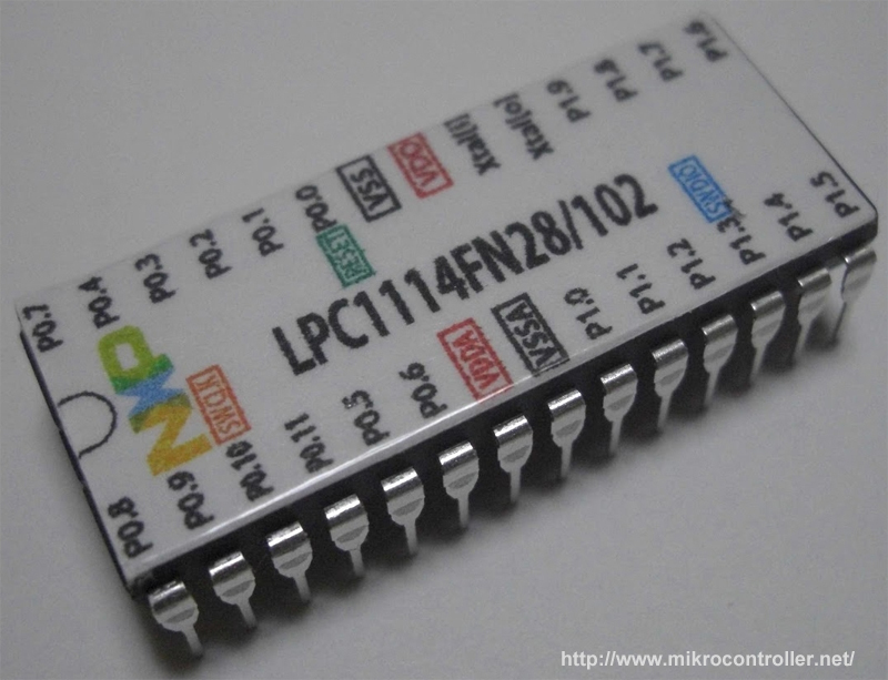
The LPC1114 in DIP28 packaging (note that most just have an unhelpful black finish instead)
There are several reasons why a microprocessor might reset itself:
- it might have crashed due to a software error
- maybe the software told it to reset itself (e.g. after a code upgrade)
- the chip may have locked up, in which case it is reset by a hardware watchdog
- perhaps the chip voltage dropped below an acceptable level, triggering a reset
- it could have woken up from deep power down mode
- or, of course, it could have just been powered on
Software running on the chip usually needs to know why it was suddenly reset. For instance, if it was reset by a brown-out event, the software might take that to mean that it’s using too much power, and fall back to a low-power mode. If the chip locked up, that may indicate a hardware failure, and the software may wish to send out an alert and shut itself down to prevent unexpected operation.
Hardware support for reset status detection
Clearly, detecting the cause of a hardware reset can’t be done purely in software for anything other than software resets: hardware assistance is required. Fortunately, LPC microcontrollers come with a variety of peripherals which make this easy. In particular, the SYSCON (system configuration) block has a register called SYSRSTSTAT (system reset status register) which can be examined to determine the “source of the latest reset event”. For the LPC1114, for instance:
- bit 0 indicates a power-on reset event
- bit 1 indicates an external reset (a sigal on the
RESETpin) - bit 2 indicates a watchdog reset
- bit 3 indicates a brown-out detection reset
- bit 4 indicates a software reset
Therefore you could do something like this on startup:
if (LPC_SYSCON->SYSRESSTAT & SYSRSTSTAT_BOD) {
    /* do something to respond to brown-out */
}
You should probably write 1’s to all the used bits in this register to clear them (yes, you need to assert the bits, not zero them) after you’ve read them, otherwise they will carry over from one reset to the next, which will make it impossible to determine the most recent reset event; the only event that will clear out the register is a power-on event, as explained by the user manual:
The POR event clears all other bits in this register. If any reset signal – for example EXTRST – remains asserted after the POR signal is negated, then its bit is set to detected in this register.
Note that some reset events may also be caught before the chip is actually reset. In particular, it’s possible to configure the LPC1114 to trigger an interrupt on brown-out before it resets, by setting the interrupt voltage threshold higher than the reset threshold. However, the software may potentially only have a very short interval of time available to it if the voltage is going to drop below the reset threshold, potentially less than a microsecond (barely enough to execute a couple dozen instructions). Therefore the software can do very little here besides toggle a few GPIO pins to e.g. turn off a motor or toggle a LED.
Storing information across software resets
So this covers hardware reset detection, now how would one distinguish between different types of software resets? Since the chip memory is cleared upon reset, we can’t store information there. An obvious solution is to store that information in some kind of non-volatile memory, such as an EEPROM module, or even the chip’s flash module. But those solutions are fairly slow, prone to faults, and in the case of EEPROM require a separate module (most LPC microcontrollers don’t have one built-in). Can we do better?
It turns out that all LPC chips come with a handful of registers which are not cleared unless the chip completely loses power! These are named GPREG0 through GPREG4 in the power monitor unit (PMU). Since a software reset does not involve powering off the chip, we can use them to store information across resets. Their size is very limited (149 bits on the LPC1114 chip for instance) but that is a problem for software to deal with!
Note that GPREG4 is partially used for other stuff, so you don’t get a full 32 bits out of it: only the high 21 bits are usable, the lower 10 bits are reserved and the remaining bit is used to control hysteresis settings on the wakeup pin.
As far as I can tell, these features are consistent across most, if not all, LPC microcontrollers.
comments powered by Disqus