A convenient circuit for testing I2C and SPI devices
Since I am currently working on integrating different devices into my bare metal kernel using the LPC1114’s hardware peripheral controllers, I figured I needed a reasonably convenient way to plug those devices onto a breadboard without spending too much time fiddling around with circuitry. This is what I came up with, feel free to use it as inspiration if you find it useful:
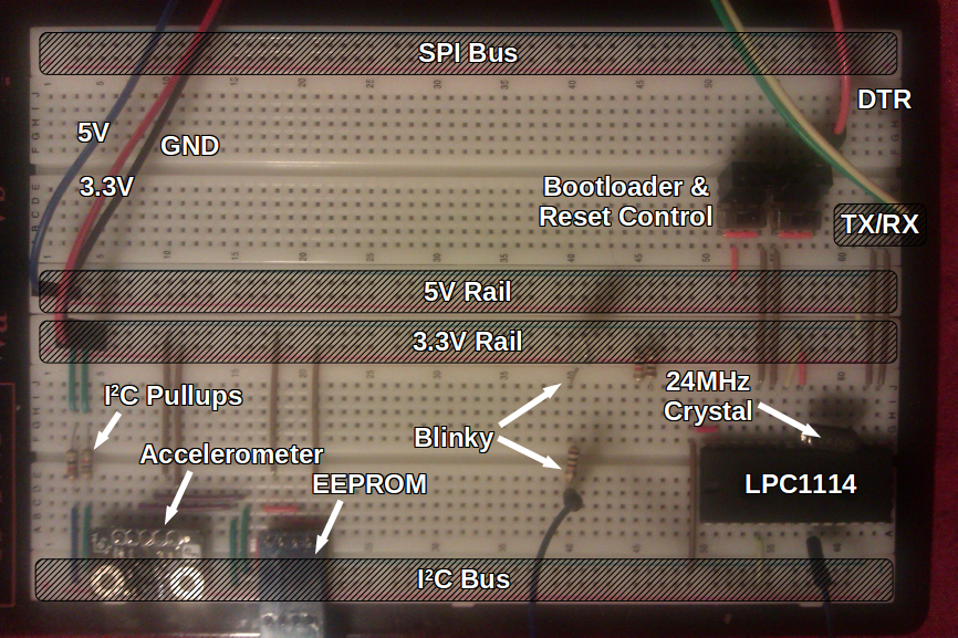
My circuit, with an I2C bus and a (currently unused) SPI bus.
It’s connected to a generic FTDI adapter with a 5V pin, a 3.3V pin, GND, TX/RX and DTR pins. I use the DTR pin to upload new software to the LPC1114 using its UART bootloader; it’s a bit annoying that my FTDI adapter doesn’t break out RTS so that I would only have to tweak one switch instead of two, currently to flash the LPC1114 I need to flick both switches on, which:
- causes
P0_1to be pulled low, telling the bootloader to enter ISP mode on reset - causes
RESETto be under the control oflpc21isp, letting it upload the code
Then I need to flick the leftmost switch first (to prevent the device reentering ISP mode upon reset) and then the other switch to actually reset and start executing the new code. However, the switches are much more convenient than having to physically move wires around every time.
The crystal is of course optional, since the LPC1114 has an internal oscillator, however the crystal is (supposedly) more accurate and I wanted to learn how to configure the Cortex M0 microprocessor to use it; turns out it’s really simple, just a single bit to flip in the PLL setup.
So far I haven’t really needed the 5V rail, as most of these breadboard-friendly devices are targeted at Arduino users and are for the most part 3.3V-5V compatible, however it’s good to know it’s there if I ever need it.
I am also thinking of sticking a current sensor between the VCC and GND of the microcontroller so I can monitor how much power it (not the whole circuit) draws, which will be very useful once I start experimenting with the Cortex power profiles and deep sleep features. The current sensor would probably be less accurate than just jamming a multimeter in there, but it would be less bulky in my opinion; I’ll have to try both and see which works better.
My kernel is at the stage where I can start interacting with multiple devices concurrently and in a coherent way, which is pretty nice, and I definitely owe that to this efficient code/upload/test workflow; it’s much easier and far less tedious to prototype when it takes five seconds to get a new build running on the device instead of half a minute.
comments powered by Disqus