Backplane interfaces for embedded devices?
I’ve long been interested in plug-and-play interfaces such as PCI or PCI Express, especially those with extensible backplanes, and have been looking into creating some edge-connector cards for my own embedded, low-cost/low-power projects, where complex, multi-layer protocols such as PCI are too complicated and unnecessary yet some flexibility is desired after assembly, without having a mess of wires everywhere.
Unfortunately I did not find any kind of standard for card-edge connectors for hobby hardware development, the closest I could find were stacked-board designs like Arduino shields, which are nice but have their own problems. So I figured I would come up with my own simple design.
Obviously due to the limited pin count available, a bus-oriented design goes almost without saying. Furthermore it would be good for the interface to be able to scale to reasonably fast speeds as needed, which calls for a few parallel lanes since we are not going to be running multi-hundred megahertz signals on low-cost microcontrollers anyway. Something like 8 lanes running at any frequency up to 40-50 MHz would be quite nice to have.
In addition I would like the protocol to be somewhat reliable, with some kind of acknowledgment of each transaction and basic error checking like a CRC32; SPI is nice and all but is not useful by its own in many cases as it is often necessary to know if a message was physically received, let alone processed successfully, by a slave device, or the master (unless you like working with corrupt data). But I haven’t yet decided if this should exist in the link layer or be moved at a higher level in the stack.
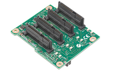
In the interest of reducing connector costs, I intend to repurpose the PCI Express hardware connectors (the small x1 ones) for my own physical interface. I don’t much like doing this as that form factor was designed specifically to prevent plugging in incompatible devices, however it’s just not economical to use a custom connector, and it is unlikely to cause issues anyway. This gives us 36 pins to work with (18 on each side) which is plenty to do something nice with.
The next steps are to flesh out the protocol and test an implementation of it with a couple of Arduinos (for simplicity) and then designing a prototype board – basically a breadboard with the card edge connector on one edge and maybe a couple passives – and a 1-slot backplane connected to a microcontroller. I hope to make another post when I have a working protocol as it will probably help to try and explain it, I have a few disjointed ideas but nothing fully formed yet.
comments powered by Disqus